The reason why the lithium battery (rechargeable type) needs protection is determined by its own characteristics. Because the material of the lithium battery itself determines that it cannot be over-charged, over-discharged, over-current, short-circuited, and ultra-high temperature charge and discharge, so lithium battery or battery pack will always appear with a delicate protection board and a current fuse.
Lithium battery protection function
The protection function of the lithium battery is usually completed by the protection circuit board and PTC and other current devices. The protection board is composed of electronic circuits. It accurately monitors the voltage of the cell and the charging and discharging circuit at all times under the environment of -40 ℃ to +85 ℃ Current, timely control the on and off of the current loop; PTC prevents the battery from being damaged badly under high temperature environment.
Ordinary lithium battery protection boards usually include control ICs, MOS switches, resistors, capacitors and auxiliary devices FUSE, PTC, NTC, ID, memory, etc. Among them, the control IC controls the MOS switch to turn on under all normal conditions to make the cell and the external circuit conduct, and when the cell voltage or loop current exceeds the specified value, it immediately controls the MOS switch to turn off to protect the cell Safety.
When the protection board is normal, Vdd is high level, Vss and VM are low level, and DO and CO are high level. When any of Vdd, Vss and VM parameters change, the level of DO or CO terminal will be changed.
Lithium battery protection board principle
Lithium battery protection board includes all above functions, here is a diagram to explain in theory:
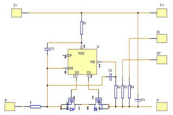
When the protection board is normal, Vdd is high level, Vss and VM are low level, and DO and CO are high level. When any of Vdd, Vss and VM parameters change, the level of DO or CO terminal will be changed.
- Over-charge detection voltage: Under normal conditions, Vdd gradually increases to the voltage between VDD and VSS when the CO terminal changes from high level to low level.
- Over-charge release voltage: In the charging state, Vdd gradually decreases to the voltage between VDD and VSS when the CO terminal changes from low level to high level.
- Over-discharge detection voltage: Under normal conditions, Vdd gradually decreases to the voltage between VDD and VSS when the D O terminal changes from high level to low level.
- Over-discharge release voltage: In the over-discharge state, Vdd gradually rises to the voltage between VDD and VSS when the DO terminal changes from low level to high level.
- Over-current 1 detection voltage: Under normal conditions, VM gradually rises to the voltage between VM and VSS when DO changes from high level to low level.
- Over-current 2 detection voltage: In the normal state, VM rises from OV at a speed of 1ms or more and 4ms or less to the voltage between VM and VSS when the DO terminal changes from high to low.
- Loading short-circuit to detect voltage: Under normal conditions, VM starts from OV and rises to a voltage between VM and VSS when the DO terminal changes from high level to low level from 1 μS to 50 μS.
- Charger detection voltage: In the over-discharge state, VM gradually decreases from OV to DO to HV when DO changes from low level to high level.
- Current consumption during normal operation: In the normal state, the current flowing through the VDD terminal (IDD) is the current consumed during normal operation.
- Over-discharge current consumption: In the discharge state, the current (IDD) flowing through the VDD terminal is the over-current discharge current consumption.
Typical lithium battery protection circuit
Due to the chemical characteristics of the lithium battery, during normal use, the chemical positive reaction between the electrical energy and the chemical energy is carried out inside, but under certain conditions, such as overcharging, over discharging and over current will cause the internal battery A chemical side reaction occurs, which will seriously affect the performance and service life of the battery after the intensification of the side reaction, and may generate a large amount of gas, which causes the internal pressure of the battery to increase rapidly and then explode to cause safety problems. Therefore, all lithium batteries need a protection Circuit, used to effectively monitor the battery's charge and discharge status, and turn off the charge and discharge circuit under certain conditions to prevent damage to the battery
The following figure is a schematic diagram of a typical lithium battery protection circuit.
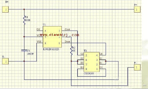
As shown in the figure above, the protection circuit consists of two MOSFETs (V1, V2) and a control IC (N1) plus some resistance-capacitance components. The control IC is responsible for monitoring the battery voltage and loop current, and controls the gates of the two MOSFETs. The MOSFET acts as a switch in the circuit, which controls the turn-on and turn-off of the charging circuit and the discharging circuit respectively. With over-charge protection, over-discharge protection, over-current protection and short-circuit protection, its working principle is analyzed as follows:
- Normal state
Under normal conditions, the "CO" and "DO" pins of N1 in the circuit output high voltages, and both MOSFETs are in the on-state. The battery can be charged and discharged freely. Because the on-resistance of MOSFET is very small, it is usually 30 milliohms, so its on-resistance has little effect on the performance of the circuit. The current consumption of the protection circuit in this state is μA level, usually less than 7μA.
- Overcharge protection
The charging method required for lithium-ion batteries is constant current / constant voltage. At the beginning of charging, the constant current is charged. In the charging process, the voltage will rise to 4.2V (according to the positive electrode material, some batteries require a constant voltage value of 4 .1V), turn to constant voltage charging until the current becomes smaller and smaller. When the battery is being charged, if the charger circuit loses control, the battery voltage will continue to be charged after a constant voltage of 4.2V. At this time, the battery voltage will continue to rise. When the battery voltage is charged to more than 4.3V, The battery ‘s chemical reactions will increase, which will lead to battery damage or safety problems. In a battery with a protection circuit, when the control IC detects that the battery voltage reaches 4.28V (this value is determined by the control IC, different ICs have different values), its "CO" pin will change from high voltage to zero voltage , Making V2 turn from on to off, thus cutting off the charging circuit, so that the charger can no longer charge the battery, and plays an overcharge protection role. At this time, due to the presence of the VD2 body diode VD2, the battery can discharge the external load through the diode. There is a delay time between the time when the control IC detects that the battery voltage exceeds 4.28V and when the V2 signal is turned off. The length of this delay time is determined by C3, usually set to about 1 second, to avoid interference caused by interference Misjudge.
3. Short circuit protection
When the battery is discharging the load, if the loop current is so large that U> 0.9V (this value is determined by the control IC, different ICs have different values), the control IC determines that the load is short-circuited, and its "DO" pin will quickly change from high voltage to zero voltage, making V1 turn from on to off, thus cutting off the discharge circuit and playing the role of short circuit protection. The delay time of short circuit protection is extremely short, usually less than 7 microseconds. Its working principle is similar to over-current protection, but the judgment method is different, and the protection delay time is also different. In addition to controlling the IC, there is an important element in the circuit, MOSFET, which acts as a switch in the circuit. Because it is directly connected between the battery and the external load, its on-resistance has an effect on the performance of the battery. As a result, when the selected MOSFET is better, its on-resistance is very small, the internal resistance of the battery pack is small, and its load carrying capacity is also strong, and it consumes little power when discharging.
- Over-current protection
Due to the chemical characteristics of lithium-ion batteries, battery manufacturers stipulate that the maximum discharge current cannot exceed 2C (C = battery capacity / hour). When the battery discharges beyond 2C, it will cause permanent damage to the battery or safety problems. During the normal discharge of the load to the battery, when the discharge current passes through the two MOSFETs in series, a voltage will be generated across the MOSFET due to the on-resistance of the MOSFET. The voltage value U = I * RDS * 2, RDS is a single MOSFET on-resistance, control the "V-" pin on the IC to detect the voltage value. If the load is abnormal for some reason, the loop current is increased. When the loop current is so large that U> 0.1V (the value Determined by the control IC, different ICs have different values), the "DO" pin will change from high voltage to zero voltage, making V1 turn from on to off, thus cutting off the discharge circuit and making the current in the circuit zero , Play the role of over-current protection. There is also a delay time between the time when the control IC detects the overcurrent occurrence and the turn-off V1 signal. The length of the delay time is determined by C3, usually about 13 milliseconds, to avoid misjudgment due to interference. In the above control process, it can be known that the overcurrent detection value depends not only on the control value of the control IC, but also on the on-resistance of the MOSFET. When the on-resistance of the MOSFET is larger, the over-current protection of the same control IC The smaller the value.
- Over discharge protection
In the process of discharging the external load, the voltage of the battery will gradually decrease with the discharge process. When the battery voltage drops to 2.5V, its capacity has been fully discharged. At this time, if you let the battery continue to discharge the load, it will cause the battery Permanent damage. During the battery discharge process, when the control IC detects that the battery voltage is lower than 2.3V (this value is determined by the control IC, different ICs have different values), its "DO" pin will change from high voltage to zero voltage, making V1 is turned from on to off, which cuts off the discharge circuit, so that the battery can no longer discharge the load, and plays an over-discharge protection role. At this time, due to the existence of V1's body diode VD1, the charger can charge the battery through the diode. In the over-discharge protection state, the battery voltage can no longer be reduced, so the current consumption of the protection circuit is required to be extremely small. At this time, the control IC will enter a low power consumption state, and the entire protection circuit power consumption will be less than 0.1μA. There is also a delay time between the time when the control IC detects that the battery voltage is lower than 2.3V and when the V1 signal is turned off. The length of this delay time is determined by C3 and is usually set to about 100 milliseconds to avoid misjudgment
Leave a comment