This is a basic tutorial to teach you each connector function of a brushless DC motor controller. It's often used when you're planning to upgrade your ebike with a new brushless DC motor controller.
Usually you may come across a problem that the DC controller does not come with a user menu, sometimes a user manual isn't bright on the box but it's all in Chinese, so the instruction is pretty much useless. Even you turn to Google Translate for help, you may still unclear as to what exactly the translated label means. So how to figure out the function of the controller?
There's a way to figure this out and now showed you how:
Basically the most critical connectors you must use in order for it to be functional are
- The power connector to the battery
- The three-phase power connector to the motor
- The hall sensor connector to the motor
- The Throttle cable connector
- Self-Learning wires
- Other connectors have extra functions you might or might not need and it's not necessary to connect those.
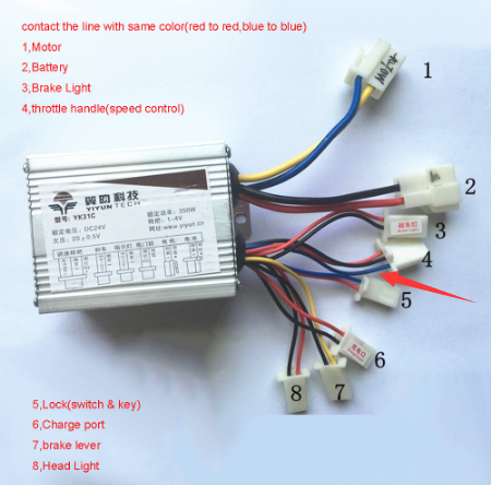
This is a normal brushless DC controller that we can get in market. Each connector marked with functions.

Picture1: The normal ebike motor controller in web
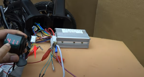
However, sometimes , we may get a controller without any English user manual, like this one in my hand.
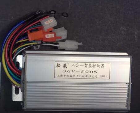
And this controller is what we'll talk about mainly, it has most the same function connectors with above picture showed controller.
First let's talk about the main power connector :
It usually has two big wires (the main positive and negative wire, which will go to the battery some times the Controller battery cables also come with 3 wires, with a smaller red wire and this is the switch wire so when you connect this wire to the main positive the system will turn on.
The switch wire is usually marked as lock line now in picture1, It controls the whole system on and off.
Usually it consumes about 0.05- 0.06 amp when the switch is turned on and when a system is idle the 0.06 amp is not much, but it will completely drain this bikes battery if you leave it on for five days.
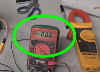
Phantom load: 0.06A. In 5 days(or 120hours), it consumes 0.06x120=7.2Ah. My bike battery pack is only 7.5Ah, so after 5days, it will almost completely drain down the whole battery pack.
So please check your controller phantom load if the system is on with idle , and make sure when you don't use the bike anymore make sure you turn this off.
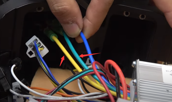
Next, let's talk about the motor cables:
This cable always has three wires and three colors like this blue green and yellow, so all you do is to match up this color from the controller to your motor wires and you're good to go.
Sometimes when you hook them up even when you match these three colors the motor still spins backwards so all you do is to switch out these two colors( green and yellow )and it will spin forward again.
If you 're not sure how to do it or worry that may burn your controller, here is a guide to connect the motor with your controller motor cables, you can verify the correct collection step by step.
For the 3 phase wires (motor cables in ESC), there are 6 possible combinations of wiring to the controller. It is good to use a piece of paper to write down the combinations so you can keep track of which ones have been tried. For each phase combination, there are 6 possible hall signal combinations. This gives a total of 36 possible configurations that may need to be tested.
If we label the motor wires A, B, and C and the controller wires Y (yellow), G (green) and B (blue), the combination table looks like this:

For each attempted combination, apply power and slowly advance the throttle while watching the current.
Incorrect combinations will have different effects depending on the combination.- Some combinations will result in the motor vibrating or not moving, but the current rises rapidly with throttle... bad.
- Some combinations will result in the motor running, but the current will become excessive at higher speeds... bad.
- Some combinations will result in the motor running backward... bad.
- When you get the right combination, the motor will start from any position, run forward and the no-load current will be in the 'expected' range...good
Be very careful when swapping the hall signal wires around. If a hall signal wire makes contact with the hall supply, there is a good chance of blowing the hall sensor. Best disconnect all power before swapping wires.
When swapping wires around, I found it very handy to use a barrier strip terminal block to hold the wires. In this setup, I used some connector pins from a serial connector to make swapping even quicker.
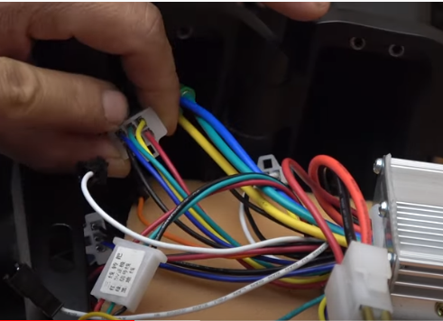
Then, here is information about the hall sensor connector
This connector almost always has five wires: black is ground , red is positive and the three other signal wires blue green and yellow and they almost always are in this order so here's what it looks like.
However not all hall sensor cables have five wires, some have six wires
For example this particular bike(Swagtron EB5) 's original motor controller with six hall sensor that comes from the motor , it's more complicated . But I found out that it works with this 5 hall sensor controllers , so I just used five of the color-coded wires and connected the hall sensor wire on the bike and I just ignore the last wire and it still works.
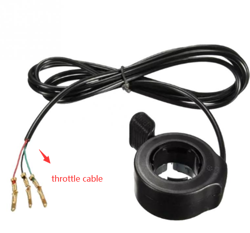
The next cable I want to talk about is the throttle cable.
It always have three wires: Red/ green(or blue) and black, it doesn't always go in this order, but basically, they represent: Positive, ground and signal. Please see normal throttle cables connectors:
But sometimes your throttle has a power button or a voltage display, then they might have more than three wires. For example, here is a picture to show the voltage display wire. Usually it has an accent wire in this wire. The marked yellow wire will go straight to the positive of the system, so after connected the yellow wire to the positive of the switch,then turn on the switch, it will show the voltage display.
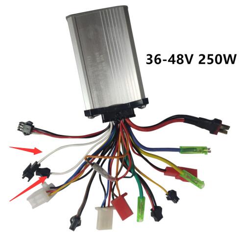
Next, I'd like to highlight the self-learning connectors
These two wires are called learning wire or sometimes I call it intelligent cable or smart wire there are many names for these wires but they are usually white.you can use these two white wires to program the motor to run forward or backward.
 And they have connectors on them and they can connect together like so
Let me show you the normal ESC with two white wire cables
They are also white. And they can connect together. Actually, you can program it to run forward and backward, and even run the model without hall sensor.
How does the self-learning wires work?
First , turn on the system
Then, connect these two wires together and when you connect this wire together it will run the motor right away and it will run in the reverse direction of whatever is programmed in the controller. (eg, if your controller is programmed to run forward so when you connect this wire together it will run wheels backward you can hear the motor running but the wheels not turning. that's because inside the motor it's got ears that prevent the wheel from running backward but you can hear the motor running and it's running backward.)
Then , use throttle to test the motor running direction . Or you can watch the motor moving direction if possible.
Next, power off the system . then the learning cable will remember the last time move direction.
Lastly, disconnect the two learning cables.
So next time, when you turn your bike on, it will run the changed directions.
If your brushless DC motor does not have a hall sensor connector( most do, some don't) you can do the same thing to program and condition your controller to run your motor this way.
The next cable that we’re going to talk about is: speed switch cable.
The wires have different colors but that's okay. The connectors look the same but it's actually for a different function which will allow you to run the motor at a higher speed than normal or at a lower speed than normal . After test the blue wire is actually higher speed and the brown wire is actually low speed.
You can use a tachometer to measure the RPM of the wheel when it's running to compare the speed between different configurations, so right now on this wire, has nothing connected to it okay so when I run my throttle it's gonna run at normal speed (518RPM) , so next I'm going to connect the black and brown cables, It’s marked as lower speed, tested the RPM is 415RPM , because at a lower voltage you will get a lower speed .And when I short the blue and black wire, tested the RPM is 533RPM.
After calculation , we count the bike speed is : 23miles/h in no loading status.

The next cable want to talk about is the brake cable.
It's got a white and black wires on it: low brake. So this will work by shutting down your system when these two wires are connected. But if you have two brakes of your bike, there is only one brake connector, how to solve it?
I'm just gonna cut this connector and sort of one more pair of wires in parallel to this so I have two pairs in order to connect to the front and rear brakes

Next thing I want to talk about is the anti theft connectors.
There’re two connectors, one is anti-theft power connector, and another one is anti-theft signal connector, it’s used for security protection of your bike. When the signal connector is connected, the bike will ring to make alarm if your bike is locked and someone try to touch on it.

Lastly, most of the controllers also have a PAS (Pedal Assist System)connector, which is used for assembly a pedal throttle. As for how to choose a throttle?to choose a pedal throttle or a hand throttle, suggest you can refer to this blog. The throttle connector that we talked about in above means the hand throttle.
Finally, Most of the common used connectors are introduced. Did you get the point? If you have any questions on it, please leave comments below this post. thanks!
I have a 750 watt motor with a 9 pin Julet plug. That’s 6 hall sensors and 3 phase wires. All the higher power, higher voltage controllers seem to use 5 hall sensors. I’ve heard that 6th one is either a heat detector or speed o meter wire. I’m probably just going to leave it unhooked. It’s white.
My bike has 6 hall wires. So if I disconnect it will it run without hurting the motor or the controller ?
Great article. Thank you!
Leave a comment