Top questions about Ubox V2 75V/100V

The Ubox V2 has two CAN sockets: in and out, the 5V pin of CAN IN socket, is just for trigger on this Ubox's own power source, the 5v pin of CAN OUT socket, can provide 5V power to other devices(eg. another Ubox V2). This will take the advantage of 12V power source of each Ubox.
2.Can I make a 4WD with Ubox V1 and Ubox V2?
Yes, V2 can be CAN cable triggered on, and let the V2 serve as secondary ESC. Do it in following steps:
step1 : Power button plug into Ubox V1 either side
step2: CAN cable connect from Ubox V1 to the CAN-in of Ubox V2.
Attention: V1 and V2 have different ESC FWs, please make sure to download corresponding firmware from our website
3. When I configuring the 4WD, the two Ubox’s behaver is confusing, what’s happening?
When combine the U-remote and two Ubox,the receiver in Ubox will report data to remote, when two Ubox are reporting to remote, they will confusing. This can be solved by disable one of the two Ubox’s receiver function:
3.1 Shutoff remote and Ubox.
3.2 Plug power button into the Ubox you want to disable
3.3 Click button to power on this Ubox.
3.4 When button’s greed LED solid, continually click the button 9 times, then wait 1S, the LED will turn off, then light again. Disable is done.
3.5 How to check the receiver is disabled?
In normal, when power on, button’s LED will blink 3S to search the remote signal. If it is no blink at all, the receiver function is disabled.
3.6 How to re-enable receiver function?
Repeat above steps, in step 4, click button 8 times, instead of 9 times.
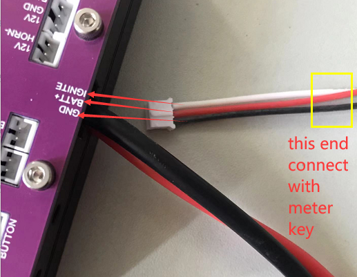
4. How do I insert the ignite key cable in port?
Attention : get aware of the principle of how ignite key working, avoid to damage ESC, since the ignite port power supply is directly from your battery!
Ignite Key working Principle: the key turns on the positive pole of the battery voltage and returns it to the start-up circuit of the controller. The function of the GND line: it provides voltage to the voltmeter together with the positive battery line.
If there is no voltage meter, then the GND line can be left unconnected theoretically.
4.1 for 75v V2 beta version, needs to open the top pannel, because the ignite port is hidden inside
4.2 for 75v V2 formall version, just insert your cable into the corresponding port
Following explains the cable information in Ubox V2 75v beta version.

there is 3pin ignite cable in accessory pack, make sure the cable order is corresponding with the port : black-->GND, red--->Battery, white--> Ignite, and the other side connect with your voltage meter key cable accordingly.

Both 100v and 75v non beta version are inserted the ignite key cable directly, following is picture of showing 100v
